Learning how to weld aluminium plate correctly requires more than choosing the right machine. Aluminium conducts heat rapidly, while its oxide layer melts at a much higher temperature than the base metal. This combination can create weak fusion, contamination, and sudden burn-through. It looks simple. It is not.
John C. Lippold, a leading welding metallurgy authority, states, “Aluminium welding demands careful control of heat, cleanliness, and joint design.” This principle guides the practical advice in this China best guide. It applies to fabrication shops, repair work, and controlled production environments. Experienced welders know that preparation often decides the result before the arc starts. Use a dedicated stainless-steel brush, remove oil completely, and keep the plate dry. A bright surface is helpful, but it does not guarantee a sound weld.
This guide explains how to weld aluminium plate correctly through material selection, joint preparation, machine settings, shielding gas, and torch movement. It also compares MIG and TIG methods for different plate thicknesses. For example, a 3-millimetre plate may distort quickly under excessive heat. A wider gap may also increase penetration problems. Small details matter. I should acknowledge one limitation: no single setting suits every aluminium alloy, thickness, or welding position. Even careful recommendations need testing on scrap plate. Check the bead profile, listen to the arc, and inspect the finished joint. A clean appearance can still hide incomplete fusion. Reliable welding comes from repeatable preparation, measured adjustments, and honest inspection.
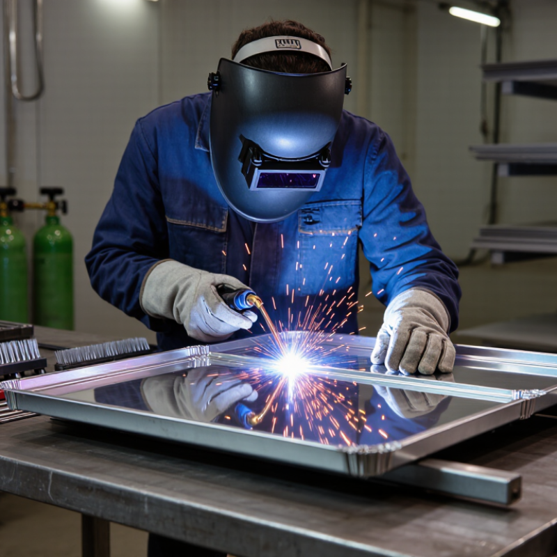
Aluminium plate welding begins with material control, not the torch. The International Aluminium Institute reported global primary aluminium production above 70 million tonnes in 2023, showing the material’s industrial importance. Aluminium conducts heat rapidly, so thick plates often need controlled preheating and stable travel speed. Check the alloy, thickness, and temper before selecting filler metal. Do not guess.
Cleanliness is critical. Remove oil with a suitable solvent, then use a stainless-steel brush reserved for aluminium. A TIG setup with alternating current suits precise work, while a MIG setup is efficient for longer joints. Use pure argon, correct shielding flow, and a short arc length. Excessive gas flow can create turbulence and porosity. The AWS structural welding specification recommends qualified procedures, suitable filler selection, and inspection for aluminium structures.
Safety remains practical, not decorative. Wear a properly shaded helmet, flame-resistant clothing, gloves, and leather footwear. Provide local exhaust ventilation because welding fumes and ozone can irritate the lungs. Keep combustible materials away, and inspect cables, regulators, and gas connections before striking an arc. Aluminium’s bright surface can hide incomplete fusion, especially on fillet joints. I still underestimate how quickly a clean plate becomes contaminated in a busy workshop. A small pause helps. Record amperage, travel speed, preheat temperature, and visible defects for repeatable results.
Aluminum conducts heat rapidly, so welding requires controlled heat input, thorough surface cleaning, and suitable shielding gas. The values shown are representative room-temperature thermal conductivity values in W/m·K; the exact value may vary with alloy temper and product condition.
China Best Guide How to Weld Aluminium Plate Correctly?
How to Prepare Aluminium Plates and Set Up the Welding Equipment
Clean preparation determines whether an aluminium weld becomes sound or porous. Aluminium melts near 660°C, while its oxide layer melts above 2,000°C, according to ASM Handbook, Volume 6A. Remove oil with a clean solvent, then scrub the surface using a dedicated stainless-steel brush. Never use a brush previously used on steel. Keep it dry.
Check the plate edges for dents, moisture, and heavy oxide. Maintain the joint gap and fit-up specified in the welding procedure. A loose joint can increase burn-through risk. For TIG or MIG welding, use high-purity argon and confirm gas flow with a calibrated meter. A practical starting range is 15–20 L/min, adjusted for nozzle size and drafts. The American Welding Society recommends matching settings to qualified procedures, not guesswork. That matters.
Connect the work lead tightly and inspect the torch, liner, contact tip, and shielding hose. Aluminium wire feeds poorly through contaminated or overly long liners. Use AC balance for TIG when the procedure requires oxide cleaning, and control preheat carefully. Many specifications limit preheat near 120°C, but the approved procedure takes priority. I have seen clean-looking plates fail after welding because fingerprints remained near the joint. Check twice. Do not trust appearance alone. Record amperage, voltage, travel speed, and gas flow for repeatable results.
| Stage | Technical Dimension | Recommended Practice | Typical Values or Selection Guide | Quality and Safety Check |
|---|---|---|---|---|
| 1. Identify the Material | Aluminium alloy and temper | Confirm the alloy, thickness, temper condition, and applicable welding procedure before selecting filler metal and process. | Common weldable plate groups include 5xxx and 6xxx alloys. Heat-treated 6xxx alloys may lose strength in the heat-affected zone. | Use material certificates or positive material identification when the alloy is unknown. Do not rely on appearance alone. |
| 2. Prepare the Plate | Joint fit-up | Remove burrs, maintain a consistent root opening, and align the plates without excessive restraint. | For butt joints, a small root gap is commonly used to support penetration; the exact gap depends on thickness, joint design, and welding procedure. | Check that edges are square, clean, and free from laminations, cracks, and sharp burrs. |
| 3. Remove Contamination | Oil, grease, moisture, and dirt | Degrease the joint area with a suitable solvent and allow the surface to dry completely. | Clean at least the joint area and adjacent surfaces before brushing or welding. Repeat cleaning if the plate is handled afterward. | Use clean, lint-free wipes. Keep solvents away from ignition sources and follow the safety instructions for the product used. |
| 4. Remove the Oxide Layer | Aluminium oxide film | Use a dedicated stainless-steel brush or approved mechanical method reserved for aluminium. Brush in one direction immediately before welding. | The oxide melts at a much higher temperature than aluminium, so oxide removal is essential for stable arc starting and sound fusion. | Do not use a brush contaminated with carbon steel, paint, or other metals. |
| 5. Select the Process | Welding method | Choose the process according to plate thickness, production rate, appearance, access, and required control. | AC TIG is suited to precise control and thinner sections. MIG aluminium welding is generally faster and suitable for longer production welds. | Use a qualified welding procedure for pressure, structural, transportation, or safety-critical applications. |
| 6. Choose the Filler Metal | Filler wire or rod compatibility | Select filler metal based on the parent alloy, required strength, corrosion resistance, crack resistance, and service temperature. | Common filler families include aluminium-silicon and aluminium-magnesium types. The correct choice must be confirmed against the base alloy and design requirements. | Keep filler metal dry, clean, and protected from dust and oil. Use the filler classification specified by the welding procedure. |
| 7. Set Up TIG Equipment | Polarity and current type | Use alternating current with high-frequency arc starting for most aluminium TIG work. | AC provides oxide-cleaning action while also supplying penetration. Balance and frequency settings should be adjusted according to the machine, alloy, and joint. | Confirm correct torch connections, secure work return, intact cables, and proper cooling-system operation where applicable. |
| 8. Set Up MIG Equipment | Wire feeding system | Use equipment configured for soft aluminium wire, including an appropriate liner, contact tip, drive rolls, and a short, straight torch cable path. | Push-pull or spool-fed arrangements can improve feeding reliability, especially with small-diameter aluminium wire. | Check for bird-nesting, excessive drive-roll pressure, worn contact tips, and restrictions in the wire path. |
| 9. Shielding Gas | Gas type and flow | Use clean, dry argon shielding gas and verify that the regulator, hose, fittings, and torch are leak-free. | Typical starting flow: approximately 10–15 L/min for TIG and 12–20 L/min for MIG, subject to torch design, nozzle size, and workplace drafts. | Excessive flow can cause turbulence and draw air into the shielding zone. Protect the arc from wind. |
| 10. Electrode Preparation | TIG tungsten electrode | Use a clean, correctly sized tungsten electrode and grind it with equipment dedicated to tungsten preparation. | A pointed or lightly truncated tip may be used according to the AC waveform and machine settings. Electrode diameter is selected according to current. | Prevent tungsten contamination. If the electrode touches the molten pool, stop, regrind, and restart with a clean tip. |
| 11. Starting Parameters | Current, voltage, and travel speed | Begin with conservative settings and make controlled adjustments while observing arc stability, wetting, penetration, and bead profile. | For aluminium plate, current and wire-feed settings vary widely with thickness, joint type, process, torch angle, and equipment. Use qualified procedure data rather than a universal setting. | Insufficient heat may cause lack of fusion; excessive heat may cause burn-through, distortion, or excessive loss of temper. |
| 12. Preheating | Plate temperature | Use preheating only when needed to improve starting conditions or compensate for a large heat sink. Heat evenly and avoid overheating. | A moderate preheat may be used when permitted by the welding procedure. The maximum allowable temperature depends on alloy, temper, thickness, and code requirements. | Measure temperature with a suitable contact or non-contact instrument. Never use an uncontrolled flame directly on the joint area. |
| 13. Welding Technique | Torch angle and travel | Maintain a short, consistent arc, steady travel speed, and sufficient shielding coverage. Keep the filler addition within the protected gas envelope. | Use a slight push technique for many aluminium MIG applications. For TIG, coordinate torch movement and filler addition without repeatedly dipping the rod into the tungsten. | Avoid excessive weaving, long arc length, sudden stops, and contaminated filler wire. |
| 14. Interpass Cleaning | Oxide and residue control | Remove visible oxide, soot, and residue between passes when multiple passes are required. | Allow the weld area to cool enough for safe handling, then clean with an aluminium-only stainless-steel brush or approved method. | Inspect each pass for pores, lack of fusion, undercut, cracks, and trapped contamination before depositing the next pass. |
| 15. Distortion Control | Heat management and fixturing | Use balanced tack welds, suitable clamping, a planned weld sequence, and the lowest practical heat input that achieves fusion. | Short weld segments, alternating sides, and skip sequences can reduce distortion in thin plate when permitted by the joint design. | Do not over-restrain the joint, because excessive restraint can increase residual stress and cracking risk. |
| 16. Final Inspection | Weld appearance and integrity | Clean the completed weld and inspect the bead profile, tie-in, crater, surface pores, undercut, overlap, cracks, and burn-through. | Acceptance limits must come from the applicable drawing, code, specification, or qualified welding procedure. | Use visual inspection as a minimum. Add dye penetrant, radiographic, ultrasonic, or other testing when required by the application. |
| 17. Workplace Safety | Personal protection and ventilation | Wear a suitable welding helmet, flame-resistant clothing, gloves, safety footwear, and eye protection. Provide effective fume ventilation. | Shield nearby personnel from arc radiation and control combustible materials, compressed-gas cylinders, cables, and hot metal. | Aluminium welding can generate intense ultraviolet radiation and metal fumes. Follow local occupational safety requirements and gas-cylinder procedures. |
| 18. Procedure Qualification | Documentation and repeatability | Record alloy, thickness, joint design, filler classification, shielding gas, polarity, parameters, preheat, interpass temperature, and inspection results. | Use a qualified welding procedure specification for repeat production or regulated work. | The values in this table are practical starting guidance; the approved procedure and applicable standards take precedence. |
Aluminium plate demands clean preparation and controlled heat. I usually remove oxide with a dedicated stainless-steel brush before welding. Even small grease marks can create pores. TIG welding suits thin plate, visible joints, and precise heat control. AC current helps break the oxide layer. MIG welding is faster for thicker plate and longer seams. However, speed can hide poor penetration.
Choose the filler rod according to the base alloy and the joint’s service needs. A 4043-type filler often produces smooth welds with reduced cracking risk. A 5356-type filler can offer higher strength in suitable alloys. Do not select filler by appearance alone. Check the alloy certificate when available. A short test coupon can reveal cracking, weak fusion, or excessive fluidity.
Use clean, dry argon for most aluminium work. A helium blend may add heat for thick sections, but it increases operating cost. Set gas flow carefully. Excessive flow can draw air into the arc. Keep the torch close, and protect the hot weld until it cools. I once increased amperage too quickly and burned through a thin edge. That mistake reminded me to use backing support and slower adjustments. Welding results still need visual inspection and, for critical parts, qualified testing.
Welding aluminium plate correctly begins with preparation, not the arc. Confirm the alloy, plate thickness, and joint design before setting the machine. Remove oil with a clean solvent, then brush away the oxide layer using a stainless-steel brush reserved for aluminium. Do not touch the cleaned area with bare fingers. Fit the plates tightly, because wide gaps can cause burn-through and distortion.
Select a suitable aluminium filler and pure argon shielding gas. For TIG welding, use alternating current with a balanced setting suited to the material. For MIG welding, use a spool-fed system and smooth wire feeding. Set moderate amperage, voltage, and travel speed according to a qualified welding procedure. Make a short test bead on matching scrap first. Watch the puddle, not only the sound. Keep the torch angle steady and maintain a short arc length.
Tack the joint at several points to control movement. Begin with a controlled travel speed, then adjust when the puddle becomes too wide or cold. Aluminium conducts heat quickly, so the starting area may need slightly more energy. Avoid excessive preheating; it can weaken the joint or hide contamination. Clean between passes and inspect for pores, cracks, incomplete fusion, and uneven penetration. A test coupon may reveal mistakes that look acceptable on the finished plate. Recheck your settings. Small corrections often matter more than speed.
A finished aluminium weld should be inspected under bright, angled light. Look for cracks, pinholes, undercut, overlap, and uneven bead width. A smooth surface is not proof of sound penetration. I have seen attractive welds fail after hidden porosity appeared during sectioning. Check both the weld face and the plate edges. Compare the bead with the approved drawing and specified acceptance criteria.
Clean the area before judging its quality. Remove soot and loose oxide with a stainless steel brush reserved for aluminium. Use a suitable solvent on a lint-free cloth, then allow the surface to dry fully. Do not touch the cleaned joint with bare fingers. Oil can return quickly. Dye penetrant testing may reveal surface-breaking cracks, but it cannot confirm internal porosity. For critical work, qualified non-destructive testing personnel should select the correct method and record results.
Improve defective welds carefully. Mark the exact problem, remove unsound metal, and inspect the exposed groove before rewelding. Check shielding gas coverage, travel speed, torch angle, and filler cleanliness. Excessive grinding can thin the plate and create a second defect. That mistake is easy to miss. Reinspect the repaired area after cooling, cleaning, and final dressing. If the same pore pattern returns, stop changing settings randomly; investigate contamination, joint fit-up, and moisture near the work area. Every inspection record should include photographs, measurements, welder identification, and repair details.
Remove oil with clean solvent. Brush away oxide using a stainless-steel brush reserved for aluminium. Do not touch the cleaned surface with bare fingers. Fit the plates tightly to reduce distortion and burn-through.
TIG welding suits thin plate, visible joints, and precise heat control. Use alternating current to help break the oxide layer. Keep the arc short and the torch angle steady.
MIG welding works well for thicker plate and long seams. It is faster. However, speed can hide weak penetration, so inspect the bead carefully.
Match the filler to the base alloy and service requirements. A 4043-type filler often gives smooth welds with lower cracking risk. A 5356-type filler may provide higher strength in suitable alloys. Appearance alone is not enough.
Weld a short piece of matching scrap before joining the actual plate. It can reveal cracks, weak fusion, excessive fluidity, or poor penetration. A finished weld may look acceptable while hiding defects.
Clean, dry argon suits most aluminium welding work. A helium blend can add heat for thick sections, but it costs more. Excessive gas flow may pull air into the arc.
Tack the joint at several points before welding continuously. Use backing support where needed. Start with moderate settings and controlled travel speed. Wide gaps increase burn-through risk. I once raised amperage too quickly and burned a thin edge.
Clean between passes and inspect for pores, cracks, incomplete fusion, and uneven penetration. Check the starting area carefully because aluminium conducts heat quickly. Qualified testing may be needed for critical parts. Visual inspection alone can miss problems.
Learning how to weld aluminium plate correctly requires careful preparation, suitable equipment, and strict attention to safety. Start by identifying the aluminium alloy and plate thickness, then clean the surfaces thoroughly to remove oil, oxide, and moisture. Prepare a stable work area, check electrical connections, and wear appropriate protective clothing, gloves, eye protection, and ventilation equipment. Select a suitable welding process, filler rod, electrode, and shielding gas according to the material and joint design. Correct settings for current, polarity, gas flow, and travel speed help control heat and reduce distortion.
Before welding, align and secure the plates, leave an appropriate joint gap, and make test welds when necessary. During welding, keep the torch angle and arc length consistent while maintaining steady movement. Afterward, allow the joint to cool naturally, remove residue, and inspect it for cracks, pores, undercut, incomplete fusion, or deformation. Defects should be corrected by cleaning, adjusting settings, and rewelding carefully. A final visual and dimensional inspection confirms weld quality and structural reliability.

Cellar Aluminum